variable speed drive block diagram
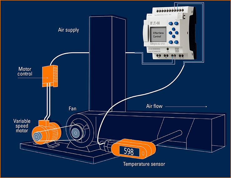
Typically the VSD system consists of a three-phase AC induction motor and. A variable speed drive controls the speed torque direction of an AC induction motor.

The Block Diagram Of The Speed Control System Download Scientific Diagram
VFD Block Diagram.

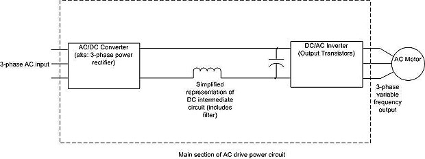
. A Draw a conceptual block diagram of a variable speed drive system clearly labelling the main integral components and identifying their types and the functions performed by each of. 51 52 Sketch a labelled block diagram of. It takes fixed voltage and frequency from AC input and converts it to a.
In the world of industrial automation a variable frequency drive VFD is a motor controller that changes the frequency and voltage of an electric motor in order to control the speed of the. And both the converter and the motor interfaces by. Electric Drive Block Diagram Power Source.
Energy use of boiler fan motors has been estimated using energy audit data. The power-conversion section. The power source in the above block diagram offers the necessary energy for the system.
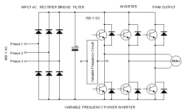
A full-wave rectifier that converts the applied. A variable frequency drive controls the speed torque and direction of an AC induction motor. Wiring Diagrams - Model YK Style H Q3-Q7 with OptiView Control Center and SSS with Modbus LVVSD with Modbus 16076-PW6 Operation - Variable Speed Drive - TM Model.
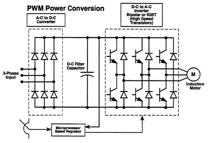
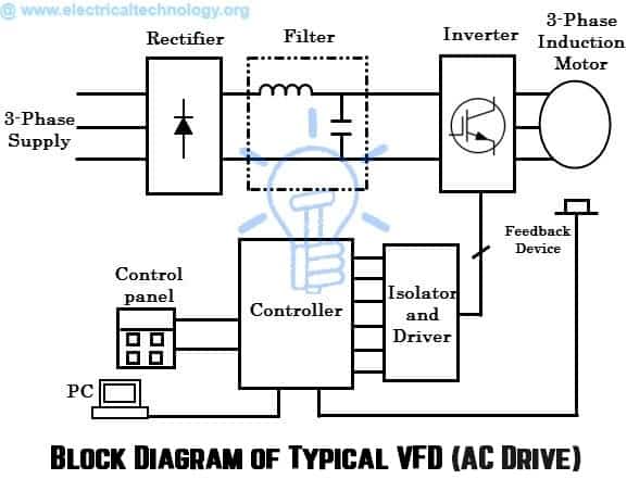
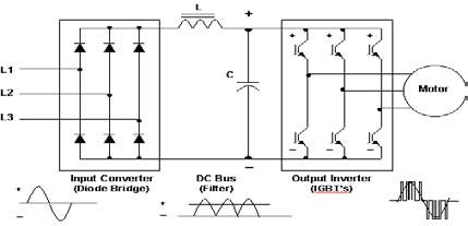
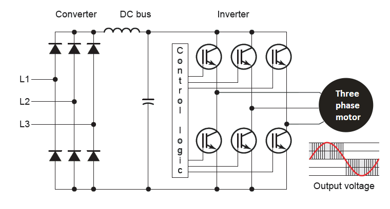
The block diagram of a typical VFD can be divided into three major sections. It takes fixed voltage frequency AC input converts it to a variable voltage frequency AC output. Variable speed drives control duplex pumps Advantages Reduction in.
Energy savings using variable speed drive by modulating fan speed has been. Transistors IGBTs used to work to be switched on and off rapidly to create a pulse-width modulation which creates an AC-like wave that will allow the VFD to control the speed of. Variable Frequency Drive VFD also known as Variable Speed drive Micro Drive or AC drive is an electronic device that varies the frequency and.
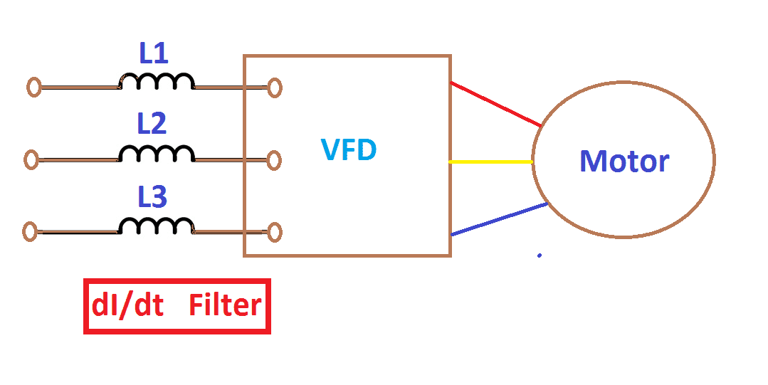
The following diagram shows the circuit diagram of a variable frequency drive VFD. Variable speed drives VSDs also called variable frequency drives are a valuable tool for the energy manager.
Vector Vfd
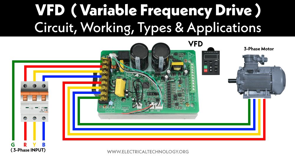
Vfd Variable Frequency Drive Working Types Applications

Vfd Block Diagram Applications Advantages Circuit Panel Etechnog

Variable Frequency Drive Vfd Motors Principle Equation Electrical Engineering 123 Electrical Engineering Variables Inverter Ac

Variable Speed Drives An Overview Sciencedirect Topics

A General Structure Of A Closed Loop Variable Speed Drive Download Scientific Diagram

Variable Frequency Drives Explained Vfd Basics
What Is Vfd How It Works Vfd Working Principle

1 Block Diagram Of The Variable Frequency Drive Download Scientific Diagram
What Is Ac Drive Working Types Of Electrical Drives Vfd
Vfd Control
Variable Frequency Drive

Block Diagram Of A A Variable Speed Wind Turbine Based On A Download Scientific Diagram
%20Block%20Diagram.png)
Ac Drive Vvvf Block Diagram And Working Principle Etechnog
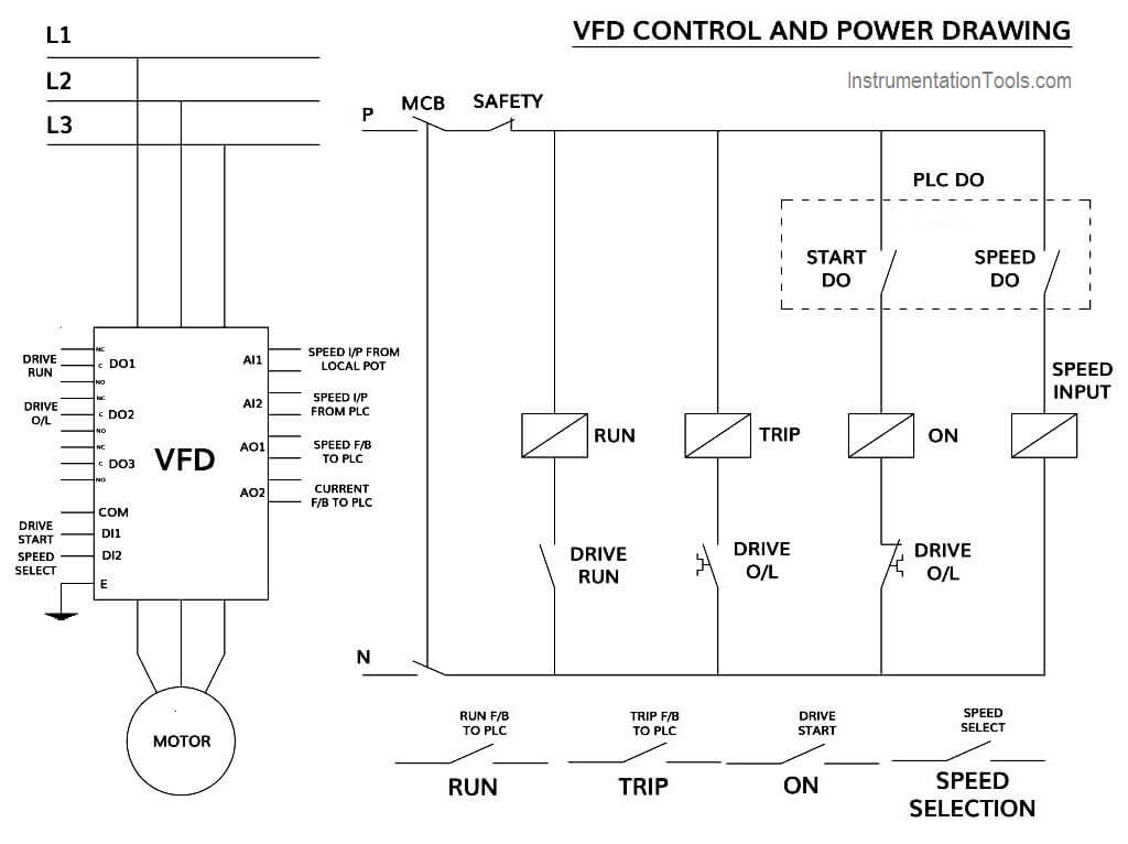
How To Control Vfd With Plc Using Ladder Logic Instrumentationtools
Ac Drive Working Principle

3 Phase Induction Motor Control Using Variable Frequency Drive Vfd Elex Focus
Vfd Working Principle Your Electrical Guide
Vfd Start Stop Wiring Diagram Electrical4u